Omni-Directional Antennas: Dipole / Rubber Duck
Omni-Directional Antennas:
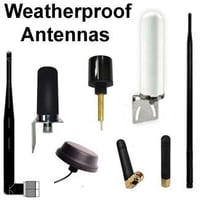
Dipole Omnidirectional Antennas come in three varieties, with regard to the base of the antenna and this variation affects weather the antenna is waterproof / weatherproof:
- Articulating right-angle is the most common form: These have a bendable angle at the base, so that they can be mounted at a 90-degree right angle, straight, or at some angle between 90-degrees and 180 degrees. This form is not waterproof / weatherproof, because water can seep in a hole, where the angle is. Therefore articulating right-angle antennas are for indoor use, or for an outside protected environment, such as under an eave.
- Fixed right angle: 90-degrees. This form is a waterproof antenna and typically is IP-rated.
- Straight (no angle): These typically have waterproof / weatherproof ratings.
The waterproof / weatherproof dipole antennas that are made of hard-plastic such as ABS, are not as durable in the weather, long-term, as fiberglass omni-directional antennas, though their low-cost makes them a viable alternative that can be replaced multiple times for less than the cost of a fiberglass antenna.
Omnidirectional antennas radiate their radio waves in all directions symmetrically on the horizontal plane, from the position of the antenna. The radio pattern of omnidirectional antennas is doughnut–shaped when viewed as an azimuth. Coverage weakens with reduced elevation as opposed to a flat horizontal environment.
Ideally omni-directional antennas achieve coverage in all directions with equal strength. But due to constraints in effectiveness of build and material, this is not perfectly achieved in practice - though a 360-degree pattern of symmetrical coverage is effectively achieved.
Dipole antennas, also called doublet, are the simplest and most commonly used RF antennas.
Dipole antennas consist of two identical conductive elements in a bilateral arrangement separated by an insulator on a common axis. The conductors are measured in total to half the length of the maximum wavelength of the RF the antenna radiates. This is referred to as a half-wave dipole antenna. The length of the conductors determines frequency and impedance of the antenna.
An electric signal is fed to both conductors from the receiver or transmitter the antenna connects to. Radio waves cause an electrical current oscillation on the conductors which is transmitted to the receiver via a pair of coaxial cables connected to each conductor.
Dipoles are reliably used by themselves as antennas, they can also be used as driven elements in complex antenna designs such as parabolic antennas, phased array and Yagi antennas.
Here are some common applications of dipole antennas:
- Dipole mast radiators
- FM broadcasting and receiving antennas
- Short wave antennas
- TV antennas (common rabbit ears)
- VHF and UHF antennas
The omnidirectional doughnut – shaped radio pattern of dipole antennas makes it effective in transmission and reception of terrestrial signals, since there is little radiation directed upwards and downwards that would otherwise be lost.
Dipole Antenna Types
Dipole antennas are available in a range of designs to suit their applications. Three of the most common types of dipole antennas are half-wave, quarter-wave and folded dipole antennas.
Half-Wave Dipole Antennas
These are the most commonly used dipole antennas. Each conductor measures a quarter the wavelength of the RF being radiated, both totaling to half the wavelength. However, in practice the conductors are slightly shorter than a half wavelength, careful calculations factoring effectiveness, diameter and dielectric constant of the material are applied.
Half-wave dipole radiates to a maximum of 2.15 dBi perpendicular to its axis, falling with the angle of elevation and off the edge of the antenna. The simple design of the dipole makes it effectively suitable for use as a driven element in complex antenna arrays such as parabolic and Yagi antennas. They can also be used on their own in several applications including:
- Dipole towers
- FM receiver antennas
- Indoor TV antennas (Set-top)
- Rabbit ears antennas
- Shortwave antennas
Quarter-Wave Dipole Antennas
A quarter-wave (also Marconi) antenna is a single element, grounded omnidirectional antenna that is one-fourth the wavelength of radiated radio frequency. Grounding the antenna causes ground reflection creating a mirror image of the antenna. This antenna design produces a low impedance feed of about 20 Ohms. The antenna radiates MF, HF, HF and VHF frequencies.
The antennas feature horizontal radials extending from the base of the antenna to improve radiation performance. In cases where a true earth cannot be used such as mobile antennas and tall masts, a simulated grounding is used; such as metallic bodies or planes. A set of radials simulating the grounded end can also be used. Coaxial cables are connected to an unbalanced feeder at the base of the antenna.
Quarter wave dipole antennas can be used in these applications due to their simplicity and effectiveness.
- Short antennas for VHF and UHF TV
- Broadcast receiver’s antennas
- Vehicle RF antennas
Folded Dipole Antennas
This is basically a dipole antenna with both ends of the dipole conductors connected by a conductive element to make a complete loop known as a fold. The connecting conductor, usually a wire or rod, runs at equidistance from the parallel pair of the dipole.
Folded dipole antennas have an increased feed impedance and a wider bandwidth. The ratio of impedance is relative to the ratio of the diameter of both conductors – the top connecting conductor, and the bottom pair of dipole conductors.
Folded dipole can be considered an extension of the basic dipole. They radiate in the same radio pattern as a half wave dipole antennas and share their basic properties. Folded dipoles can be used on their own where there is a need for high impedance feeder of up to 300 Ohms –useful in areas where a balanced feeder is needed, or coupled in complex antennas arrays such as Yagi and parabolic antennas.
They can be used in:
- Aircraft antennas
- Broadband antennas
- FM antennas
- Parabolic and Yagi arrays
- VHF and UHF TV antennas
Other less popular dipole antennas that are available both for commercial and domestic use; with varying shapes and applications include the following:
- Multiple half-wave dipole
- Non-resonant dipole
- The bow-tie antenna
- Cage dipole antenna
- Short dipole antenna
- Quadrant antenna
- The G5RV Antenna
- The sloper antenna

