Antennas, Antenna Cables, Wireless Products: Technical Articles
Antenna Cables: Definitions of Components and Terms
A
American Wire Gauge (AWG) is a wire gauging system used in electronics that works on a logarithmic scale. As the AWG number increases the actual cable cross-sectional diameter decreases. It may also be known as Brown & Sharpe Wire Gauge (B&S).
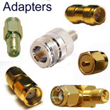
Antenna adapters are specially designed connectors that screw connect to a particular class of connector at one end and facilitate compatibility with a different class of connector at its opposite end. An example is an RP-TNC to n-type connector. A high-quality antenna adapter will maintain the electrical profile of the two connector classes with discontinuities kept to a minimum to prevent signal reflections and losses.
Antenna adapter cable is a length of coax capped with connectors that facilitate compatibility between an antenna and a downstream connection that would be otherwise incompatible. The cable may be a pigtail, as discussed further down. Examples include:
- SMA male to RP SMA female
- U.FL to SMA
- RP SMA female to RP TNC female
- FAKRA antenna adapters for car radio
Attenuation is a measure of the loss of signal strength along a length of coaxial cable - measured in decibels (dB) per length of cable, measured in meters or feet. Attenuation charts are typically provided as part of the specification of particular types of coaxial cable, to facilitate the evaluation of their performance.
B
BNC stands for Bayonet Neill–Concelman and refers to a type of standard-sized antenna connector that is coupled and secured by using a bayonet mechanism and coupling nut. Within the connector, a male pin is inserted into a female receptacle for an electrical connection. BNC connectors are available with either a 50 or 75 Ohm impedance and can support frequencies up to 4 GHz.
Brass is a copper-zinc alloy which is of particular importance as a base material for radio frequency connectors. It is easily machined and is effective in containing radio frequency energy and preventing cross-talk between electronic components. It is often plated with gold, silver, nickel, or proprietary alloys.
C
Capacitance refers to the ability of a coaxial cable to retain the electrical current within it. The capacitance of coax cable is due to the space between the inner and outer conductors and will vary with their spacing by the dielectric layer.
Coaxial antenna cable assemblies are pre-assembled antenna cables with the required connectors attached at each end. Purchasing high-quality pre-assembled antenna cables can save the expense and time of self-assembly of coax cable and connectors by soldering or crimping.
Coaxial cable, also known as coax cable , is the cable type used in antenna cable assemblies. This cable is uniquely structured to provide efficient transmission of radio frequency signals due to its high level of shielding that protects transmitted signals from external electromagnetic interference. It consists of the following layers:
- A central inner conductor is usually made from single or multiple strands of copper or copper-coated steel.
- A surrounding insulator is made from PTFE or polyethylene.
- A braided shield layer is made from tinned copper. This shielding may be doubled or covered with a special foil layer.
- An outer flexible plastic jacket.
Coaxial radio frequency connectors are electrical connectors that are specifically designed to attach to coaxial cable and maintain its structural, electrical, and functional continuity. This is essential to minimize not only signal loss but impedance mismatch and the creation of reflections at the junction between the cable and connector. Connectors are designed to form a secure mated union of complementary male and female components that may be threaded, bayonet, or press-down. A variety of types and classes of radio frequency connectors used with antenna cables are precision engineered and able to facilitate transmission at up to microwave frequencies.
Connection cables have the same gender on both ends.
Copper is used for the central conducting wire or strands in most coaxial cables, as well as the braided shield layer. It is a particularly effective conductor of electrical current and heat and is fairly resistant to corrosion. It is easy to machine and can also be used to plate coax and connector elements.
Crimping is an attachment method for joining a radio frequency connector to coaxial cable to form a cable assembly. Crimping produces a solder-free electrical connection and can be used to attach the connector pin and shank using a specially calibrated crimping tool. Key advantages of crimping over soldering of antenna cable connectors include improved mechanical strength, a gas and moisture-tight union, and convenience.
D
Dielectrics are electrical insulators that surround both the conducting wire in a coaxial cable and the inner conductor of a coaxial connector. The electrical current is unable to flow freely through this insulating layer, which carries high resistance, preventing signal loss. Dielectric diameter and completeness of enclosure will affect impedance, capacitance, and the shielding efficacy of the outer conductor. Plastics such as PTFE or PE are used as dielectrics.
E
Extension cables are coax cables capped with connectors of the same class. They have a plug of the appropriate gender on one end and a jack of the opposite gender at its other end. This cable could be capable of connecting to itself. An extension cable allows attachment of an external antenna which can be positioned at a distance from the device itself. One end of these antenna cables can be connected to the radio device and the other end of the extension cable is connected to the antenna. Ideally, the cable length is kept as short as possible to minimize signal loss along the length of the line.
F
Flexible coaxial cable is often used for creating high-speed wireless links as it can be installed in confined spaces. Its flexibility is due to a finely stranded copper inner conductor which is surrounded by a flexible polymer insulator, tinned copper braided shield (with 90% coverage), and outer plastic jacket. A second aluminum foil outer jacket can be added for extra insulation. These coax cables are relatively thin and have diameters ranging from 0.109 inches / 2.79 millimeters (RG174) to 0.405 inches / 10.28mm (RG 8). Flexible coax can be prone to kinking of both the shield and inner conductor if the bend radius is exceeded. To improve resilience, a solid wire core and insulating PTFE foam may be used. Flexible coax usually has an impedance of 50 Ohms. Examples include:
Fluoroethylenepropylene (FEP) is a plastic that is used to manufacture the outer jacket of coaxial cable. It is usually extruded and has high thermal stability and weather resistance.
Formable coaxial cable is similar to semi-rigid cable in terms of performance and is engineered to be able to be reformed multiple times by hand without damaging the coax. Most types used tinned copper braid as the outer shield. Their flexibility makes routing and layouts easy, without the need for tools.
H
Hardline coaxial cable is a heavy-duty form of coaxial cable used for long term installation. It uses solid metal shielding (often rigid copper or aluminum), a foam dielectric, and is capable of withstanding high voltages and harsh environments. It is thick, with an average diameter of 1.75 inches. It has a 75 Ohm impedance. Hardline coax is highly durable but prone to kinking so needs to be carefully handled when installed. This type of coax is often used as antenna cabling by Ham radio enthusiasts but requires specialist hardline connectors and stripping and assembly with professional tools.
I
Impedance is a measure of resistance to the flow of electrical current within the coaxial cable, connectors, and antennas and is measured in Ohms. The dielectric constant of the coax insulating layer is a key determinant of coax impedance as well as the radio of both the inner and outer conductors.
J
Jacket layers of coaxial cable are essential for protecting the outer and inner conducting layers from environmental exposure, which can cause corrosion and other forms of damage. The outer jacket is typically made from plastics such as polyethylene and PFA which can contribute to the flexibility of the cable as well as its thermal stability and resistance to corrosive substances and solvents.
Jack connectors are the fixed part of a connection. It may be wall or PCB mounted. It is the connector that is housed on or within devices or equipment and is unlikely to move significantly. It is often, but not always female, as both plugs and jacks can be of either gender. If a connector is mounted on a panel or has threads or other nut retaining devices on its outside it is called a JACK type connector. In some situations, a panel-mounted jack can have both male and female connectors. Jacks may be male or female in gender, but by far most typically, "jack" means "female." The exceptions are U.FL and MHF4 jacks, which are male in gender.
L
‘Low loss’ LMR cable is a coaxial cable type that has lower rates of signal loss compared to coaxial cabling of equivalent diameter. An example is low loss LMR 100 coax which has the same diameter as RG 174 and is commonly sought as a replacement. They typically have a solid inner conductor, high resistance dielectric, wire braid, and foil shielding within their outer jacket which all contribute to their superior performance. A notable variety of low loss cable is LMR cable which comes in the following types:
Lossy line describes a transmission line that loses a significant proportion of the electromagnetic energy transmitted along its length. Sometimes this is deliberate, as in the case of radiating cables, but it is usually a consequence of poor shielding. No line is completely lossless due to impedance and current leakages, especially as cable length increases.
M
MCX or Micro-coax connectors are connectors designed to connect to micro coaxial cable. They are snap-on connectors that are structurally comparable to SMB connectors but around a third smaller.
Micro coaxial cable also is known as mini-coax because of its small outer diameter. This lightweight miniature coaxial antenna cable has 50 Ohm impedance with low capacitance and signal loss and is usually used within devices that require high-frequency connectivity, especially where there are hinges or articulating parts. It is of particular benefit in applications where space is limited. Micro-coax retains the standard coaxial cable structure and may have a stranded center conductor and single or double shielded outer layer depending on the type. They are classified according to their outer diameter in millimeters:
MMCX connectors are miniature micro coax connectors that mate using a lock-snap mechanism and are capable of rotation at their connection. They have 50 Ohm impedance and can support frequencies up to 6 GHz. They are commonly used with internalized antennas or to facilitate the connection of an external antenna to a device.
N
N Type connectors are standard-sized threaded, weatherproof connectors that are typically paired with semi-rigid coax for antenna cables. They have impedances of either 50 or 75 Ohms and can support frequency transmissions of up to 18 GHz.
Nickel is a metal that is widely used in the manufacture of antenna cable connectors, due to its malleability and resistance to oxidation. It can be combined with other metals as an alloy or used in plating.
O
Operating frequency range denotes the bandwidth or range of frequency across which a coaxial cable or connector is expected to perform within key performance thresholds such as shielding effectiveness and propagation velocity. Operating frequency range will vary with the design and fabrication of individual types of coax, but modern antenna cables typically range from DC well into the microwave frequencies.
P
Patch cable is also known as accessory cable is a length of coax that is used to 'patch in' radio frequency components and route signals. It is fitted with the appropriate connectors at both ends, performing similarly to a pigtail. They may also have superior shielding or low attenuation making them a suitable swap-in for a more inferior grade of coax.
Pigtail cables are short lengths of coaxial cable capped with radiofrequency connectors of the same or differing types. Pigtail wire connections are useful to extend a connection to where it can be more easily accessed, for example connecting an external antenna to a PCB. Pigtails can also perform the job of an antenna adapter allowing connectors of differing sizes or caliber to be used.
Pins are the male inner contact of a radio frequency connector which is designed to insert into the receptacle of the corresponding female connector.
Plug connectors are connectors on the end of a cable which makes a mating connection with a fixed Jack. If a connector is mounted onto a cable with a concealing nut it is called a PLUG type connector. Plugs may be male or female in gender, but by far most typically, "plug" means "male."
Polyethylene (PE) is a low-density polyolefins plastic that is widely used in antenna cable manufacturing for insulators and outer jackets. It is an efficient electrical insulator and has superb water-resistance. A disadvantage is its relatively low melting temperature.
Polytetrafluoroethylene (PTFE) is a commonly used plastic that has good chemical resistance and thermal stability. It is used for the dielectric layer of many forms of coax.
R
Receptacle is the portion of the mating interface of a female connector that receives the male pin when a mechanically and electrically functional connection occurs.
Reverse Polarity SMA (RPSMA) connectors are a commonly used connector type for antenna cables. This threaded sub-miniature connector is structurally and functionally identical to the SMA connector apart from a reversal of its mating interface, meaning that a male connector carries a receptacle and the female RP-SMA connector is equipped with a conducting pin.
Reverse Polarity TNC (RPTNC) connectors are a variant of the TNC connector with deliberate reversal of the gender of the inner conductor. The male RP-TNC carries a receptacle and the female RP-TNC connector carries a pin.
RG stands for Radio Guide and refers to the original military specification system for coaxial cables devised in the 1930s. This system of grading is now obsolete and only loosely refers to cable diameter.
S
Semi-rigid coaxial cable is a type of 50 Ohm impedance coaxial cable which is favored for its flexibility and wide frequency range, including microwave performance. Flexible coax typically consists of a solid inner conductor surrounded by a polymer insulator with solid copper tubing that serves as an outer conductor and a plastic jacket. Outer diameters range from 0.047 inches (1.19 millimeters) to 0.250 inches (6.35 millimeters). This type of coax is described as semi-rigid because it is malleable and will retain its shape once conformed. Examples include:
- RG 401
- RG 405
Shielding of coaxial cables refers to layers of braided tinned copper, copper tubing, or aluminum foil that are used to protect the insulated inner conductor from electromagnetic interference. Shielding helps maintain the electrical and magnetic fields between the two conductors. It is reliant on the conducting wire being fully enclosed by a dielectric.
Skin effect refers to the tendency for alternating current to become distributed within a conductor with its greatest density at the surface of the conductor with an exponential decrease in current density towards the center of the conductor.
Soldering is a method used to create a secure attachment between a connector and a length of antenna cabling. Soldering involves the use of a soldering iron to heat a filler metal known as solder, which is used to join metal components like the center pin and shank of the connector to the coax. Properly executed soldering produces a long-lasting and reliable physical and electrical connection between the connector and the coaxial cable.
Specialty cables are neither extension cables nor connection cables and should have complete descriptions of the type and gender of each plug/jack. Specialty coaxial cables differ from standard cable because of their proprietary design, superior engineering, and performance, or the ability to withstand extreme conditions. They are usually selected for the most demanding applications and have greater capability than their generic counterparts. Examples include:
- High voltage coaxial cable
- Low loss LMR coaxial cable
- Spiral flex coaxial cable
Sub-Miniature version A (SMA) connectors are threaded connectors that are regularly used with antennas and their cabling. The male connector carries a pin and has a hex nut outer housing and internalized threads which screw down onto the female counterpart to form a 50 Ohm mated connection.
T
TNC connectors also known as Threaded Neill–Concelman connectors are standard sized 50 Ohm coaxial connectors used for frequencies up to 11 GHz. It forms a screw-down connection with the male inner pin inserting into a female receptacle to conduct the radio frequency signal.
Transmission lines are radio frequency circuits capable of carrying alternative current from a source into a load. The coaxial cable acts as a transmission line by conducting signals to and from antenna and receiver components in radio devices.
U
U.FL connectors are miniature coaxial connectors that form a snap-on, 50 Ohm impedance connection. They are often PCB mounted and are not intended for repeated mating cycles. Male connectors carry a pin and female connectors a corresponding receptacle. They are often attached to a pigtail cable length of 1.32mm coax.
V
Velocity of propagation (Vp) is a measure of the speed of signal propagation along the coaxial cable as a proportion of the speed of light.
Voltage Standing Wave Ratio (VWSR) also known as return loss measures the efficiency of transmission of radio frequency power through a cable or line from source to load. It is presented as a calculated ratio of the maximum ( Vmax) and minimum (Vmin) voltages along the transmission line caused by reflections. In a perfect radio frequency setup, 100% of the energy would be transmitted into the load, but impedance mismatch in the cable assembly will increase the ratio.


