Antennas, Antenna Cables, Wireless Products: Technical Articles
Comparison of LMR-100, LMR-200 and LMR-400 Coax for Antenna Cables
Table of Contents
Signal Loss, Specifications and Composition of LMR-100, LMR-200 and LMR-400 Compared
When designing or upgrading any RF, wireless, or antenna-based system, the coaxial cable is just as important as the antenna or radio itself. Signal loss within the cable—known as attenuation—can significantly affect system performance, especially at higher frequencies and over longer cable runs. In this article, we compare LMR-100, LMR-200, and LMR-400 coaxial cables, focusing on signal loss, shielding, construction, and real-world applications to help you select the right cable for your installation.
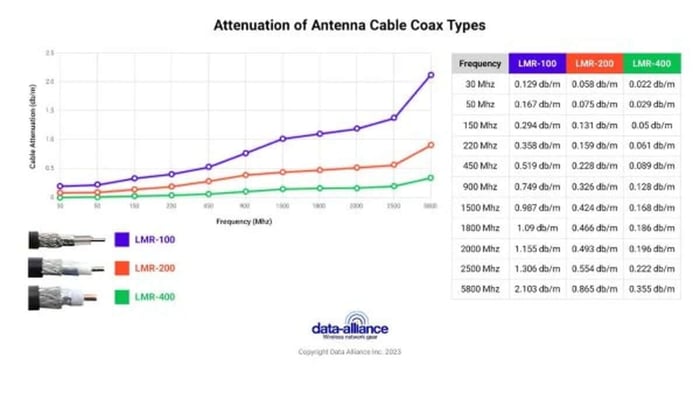
Attenuation is Loss of Signal in the Cable
Attenuation refers to the reduction of signal strength as radio frequency (RF) energy travels through a coaxial cable. This loss occurs due to conductor resistance, dielectric losses, and electromagnetic interference. Attenuation is measured in decibels (dB), and the higher the number, the greater the signal loss.
As frequency increases, attenuation also increases. This makes cable selection especially critical for applications such as cellular (LTE/5G), WiFi, GPS, and ISM-band radios, where even a few decibels of loss can noticeably impact performance.
Double shielding benefits: LMR-100, LMR-200 and LMR-400
One of the defining advantages of LMR-series cables is their double-shielded construction. LMR-100, LMR-200, and LMR-400 all feature:
- An aluminum foil layer providing 100% coverage
- A dense copper braid shield for mechanical strength and additional RF isolation
This dual-shield design offers far better signal preservation than the single-shielded RG coax types they are often compared to, such as RG-174 or RG-58. The aluminum foil acts as a continuous RF barrier, while the copper braid suppresses leakage and external electromagnetic interference (EMI).
The result is a low-loss cable that maintains signal integrity while also protecting against noise from nearby electronics, power lines, or radio transmitters—an essential feature in industrial, commercial, and outdoor environments.
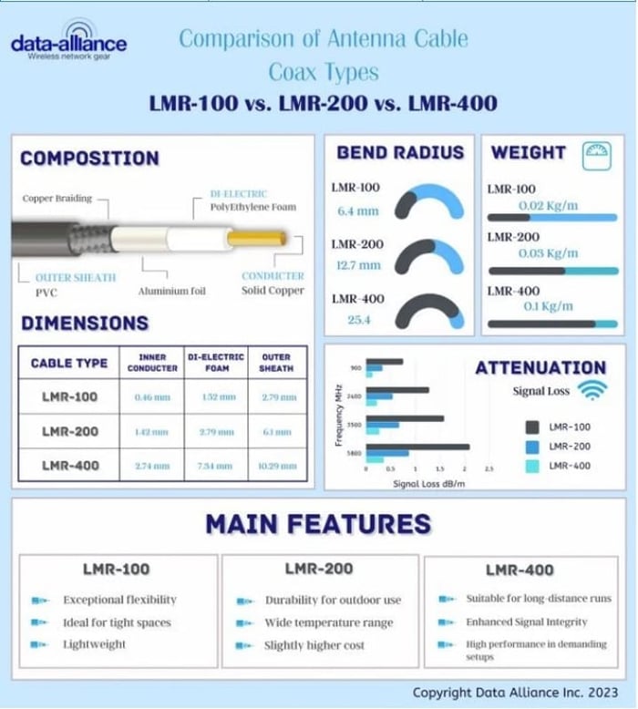
Attenuation (Loss of Signal): How do LMR-100, 200 & 400 compare?
As classified as low loss, you can probably imagine they all fare well in this category. But for further detail, please read on:
* For detailed information on the terms dBi, dB, dBm, and dB(mW) *
At 900 MHz
- LMR-100 = 0.75 dB/m. (0.23 dB/ft.)
- LMR-200 = 0.33 dB/m. (0.09 dB/ft.)
- LMR-400 = 0.13 dB/m. (0.039 dB/ft.)
At 2400 MHz
- LMR-100 = 1.28 dB/m. (0.39 dB/ft.)
- LMR-200 = 0.54 dB/m. (0.12 dB/ft.)
- LMR-400 = 0.22 dB/m. (0.066 dB/ft.)
At 3500 MHz
- LMR-100 = 1.58 dB/m. (0.48 dB/ft.)
- LMR-200 = 0.67 dB/m. (0.21 dB/ft.)
- LMR-400 = 0.27 dB/m. (0.081 db/ft.)
At 5800 MHz
- LMR-100: 2.10 dB/m. (0.64 dB/ft.)
- LMR-200: 0.87 dB/m. (0.264 dB/ft.)
- LMR-400: 0.36 dB/m. (0.108 dB/ft.)
Attenuation Summary Table
| Frequency | LMR-100 Attenuation (dB/m) | LMR-200 Attenuation (dB/m) | LMR-400 Attenuation (dB/m) |
| 900 MHz | 0.75 | 0.33 | 0.13 |
| 2400 MHz | 1.28 | 0.54 | 0.22 |
| 3500 MHz | 1.58 | 0.67 | 0.27 |
| 5800 MHz | 2.10 | 0.87 | 0.36 |
As expected, LMR-400 offers the lowest attenuation, making it the preferred choice for long cable runs or higher-frequency applications. LMR-200 provides a strong middle ground, while LMR-100 is best suited for short, space-constrained runs.
Cable Composition and How It Impacts Performance
Taking a look into the technical features (composition) of the coaxial cables, we will summarize conclusions about how they contribute to the user benefits (advantages):
- Copper clad-steel conductor - an excellent carrier of radio frequency signal, ideal for almost any cabling challenge
- Dielectric PE foam - a superior dampener of loss of electromagnetic radiation
- Double shielding - aluminium sheet plus copper braiding for maximum preservation of signal strength across length of cable
- Outer Jacket - a robust finish, ideal for maintaining functional excellence in physically challenging environments
Detailed Construction Breakdown
1. Inner conductor
- LMR-100 conductor: approximately 0.46 mm (0.02 inches) in diameter
- LMR-200 conductor: approximately 1.42 mm (0.06 inches) in diameter
- LMR-400 conductor: above 2.74 mm (0.11 inches) in diameter
Larger conductors reduce resistance and lower signal loss, which is why LMR-400 performs best over distance.
2. Dielectric foam diameter & material
- LMR-100 foam diameter: 1.52 mm (0.01 inches), Polyetylene foam
- LMR-200 foam diameter: 2.79 mm (0.001 inches), Polyethylene foam
- LMR-400 cable sheath: 7.24 mm, (0.29 inch) Polyethylene foam
Foamed dielectric improves impedance stability and reduces attenuation at higher frequencies.
3. Inner shield
- All three use copper braiding for shielding strength and flexibility.
4. Outer shield
- Aluminum foil layer providing 100% coverage in all three cables.
5. Outer cable sheath diameter, material & color
- LMR-100 cable sheath: approximate 2.79 mm (0.11 inches) diameter, Polyethylene black
- LMR-200 cable sheath: approximately 6.1 mm (0.24 inches) in diameter, Polyethylene, black
- LMR-400 cable sheath: above 10.29 mm (0.41 inches) in diameter, Thermoplastic elastomer, black
Additional Mechanical and Environmental Characteristics
- Temperature range: −40°C to +85°C
- Minimum bend radius:
- LMR-100: 6.4 mm (0.25 in)
- LMR-200: 12.7 mm (0.5 in)
- LMR-400: 25.4 mm (1.0 in)
- Weight:
- LMR-100: 0.02 kg/m (0.013 lbs/ft)
- LMR-200: 0.03 kg/m (0.02 lbs/ft)
- LMR-400: 0.10 kg/m (0.068 lbs/ft)
- Halogen-free construction for improved safety and compliance
These characteristics make LMR cables suitable for both indoor and outdoor installations, including harsh or temperature-variable environments.
Typical Applications for LMR-100, LMR-200, and LMR-400
LMR-100, LMR-200 & LMR-400 are double-shielded, low signal-loss coaxial cable types for antenna cables. As closely related "sister" coax types, they each share commonly associated characteristics and possess comparable benefits. Their purpose is simply to convey radio frequency transmitted signals across physical distance, with minimal loss or interference. Here are some typical application scenarios:
LMR-series cables are commonly used in:
- HDTV and broadcast systems
- Broadband internet networks
- CCTV and security video
- RF and two-way radio systems
- Antenna feed lines
- Wireless assemblies
- WLAN and WiFi networks
- GPS installations
- Cellular LTE and 5G systems
Cable choice typically depends on run length, frequency, flexibility requirements, and available installation space.
Conclusion
LMR-100, LMR-200, and LMR-400 coaxial cables are engineered for reliable RF signal transmission with low attenuation and strong protection against interference. Their double-shielded design, high-quality materials, and wide operating temperature range make them dependable for a variety of wireless and communication applications. While LMR-100 offers flexibility for short runs, LMR-200 provides a balance of performance and size, and LMR-400 delivers the lowest signal loss over long distances. Together, they offer scalable solutions to meet different installation needs with consistent durability and efficiency.
FAQs
What is attenuation in coaxial cables?
Attenuation refers to the loss of signal strength as it travels through a cable. It is measured in decibels per meter (dB/m) and increases with cable length and frequency.
What makes LMR cables low-loss compared to other coaxial cables like RG-58 or RG-174?
LMR-100, LMR-200, and LMR-400 use double shielding—an aluminum foil layer plus copper braid—which provides superior protection from interference and reduces signal loss.
How do LMR-100, LMR-200, and LMR-400 compare in terms of signal loss?
Signal loss decreases as cable size increases:
- LMR-100 has the highest attenuation (best for short runs)
- LMR-200 offers moderate loss
- LMR-400 has the lowest attenuation (best for long-distance runs)
What are typical applications for LMR coaxial cables?
LMR cables are used in:
- Antenna extensions
- Wireless networks (Wi-Fi, WLAN)
- GPS
- Broadband internet
- CCTV systems
- HDTV
- Radio and video communications
What materials are LMR cables made from?
They feature a copper-clad steel conductor, polyethylene (PE) dielectric foam, aluminum foil shield, copper braid, and a durable black outer jacket.
Why does cable diameter matter?
Thicker cables like LMR-400 have larger conductors, which reduce resistance and signal loss, making them ideal for long runs. Smaller cables like LMR-100 are more flexible but lose more signal over distance.
Are LMR cables suitable for outdoor use?
Yes. Their UV-resistant outer jackets and wide operating temperature range (-40°C to +85°C) make them ideal for outdoor installations.
What are the bending and handling characteristics of LMR cables?
LMR cables are designed to be flexible and easy to install:
- LMR-100: smallest bend radius (6.4 mm), ideal for tight spaces
- LMR-200: medium flexibility (12.7 mm)
- LMR-400: stiffer but still manageable (25.4 mm)

