


Antennas, Antenna Cables, Wireless Products: Technical Articles
SMA Connector Specifications, Dimensions & Applications (SMA vs RP-SMA)
The SMA connector (SubMiniature version A) is one of the most widely used RF connectors in wireless communications, valued for its compact size, excellent electrical performance at high frequencies, and reliable threaded coupling. This guide covers SMA connector specifications, dimensions, materials, panel cutouts, and torque, and explains how the SMA connector differs from RP-SMA. SMA connectors are commonly used in cellular, GPS, and amateur (HAM) radio systems, while the closely related RP-SMA (Reverse-Polarity SMA) variant is more common on Wi-Fi, Bluetooth, ZigBee, and LoRaWAN devices in the United States.
Because SMA and RP-SMA connectors look nearly identical at first glance, they are often confused or incorrectly paired. Understanding the physical, mechanical, and electrical characteristics of the SMA connector is critical to ensuring proper mating, minimizing signal loss, and preventing damage to antennas or RF devices. Browse Data Alliance's SMA cables and adapters and SMA antennas for parts that match the specifications below.
SMA Connector Specifications at a Glance
The table below summarizes the key SMA connector specifications for standard commercial and industrial versions. Precision or extended-performance SMA variants can exceed these figures, but standard SMA is more than sufficient for most wireless systems.
| Specification | Standard SMA Connector |
|---|---|
| Impedance | 50 ohms |
| Frequency range | DC (0 Hz) to 18 GHz |
| Coupling mechanism | Threaded, 1/4-36 UNS-2 |
| Body material | Gold-plated or nickel-plated brass |
| Center contact | Gold-plated beryllium copper |
| Insulator (dielectric) | PTFE |
| Female outside diameter | 5/16 in (7.9375 mm) hex |
| Bulkhead torque (standard) | ~5 in-lb (0.57 N·m) |
| Typical mating cycles | 500+ (design-dependent) |
| Common applications | Cellular, GPS/GNSS, HAM radio, test equipment |
SMA Characteristics and Key Points
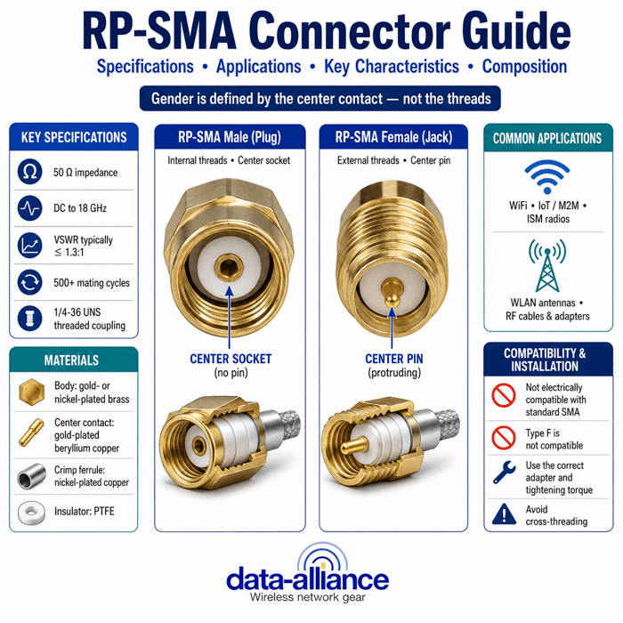
The SMA connector is a round, screw-type RF connector with medium-sized threaded coupling. It is designed to provide secure mechanical attachment, stable impedance matching, and reliable RF performance at high frequencies. Two points cause most field errors: the difference between SMA and RP-SMA, and the counter-intuitive way SMA gender is assigned.
SMA vs RP-SMA: A Common Source of Confusion
One of the most important distinctions to understand is the difference between SMA and RP-SMA. Although the connectors share the same threaded body dimensions, they differ internally.
- SMA uses a traditional pin-and-socket configuration.
- RP-SMA reverses the pin and socket while keeping the same outer threads.
As a result, an SMA connector will not electrically mate with an RP-SMA connector, even though the threads may engage. This mismatch can cause open circuits, degraded RF performance, or physical damage to the center contact. In most cases:
- SMA is used for cellular modems, GPS antennas, test equipment, and HAM radio.
- RP-SMA is commonly used for Wi-Fi routers, access points, and IoT radios in the U.S. See our RP-SMA connector specifications for a full comparison.
SMA Male vs SMA Female: Counter-Intuitive Gendering
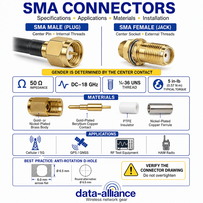
SMA gender designation is often misunderstood because it is not based on the external threads, but rather on the center contact inside the connector body.
- SMA male (plug) → has a center pin.
- SMA female (jack) → has a center socket.
This is counter-intuitive because the SMA male typically has internal threads, while the SMA female has external threads. The gender is determined solely by the pin vs socket, not the threads. Getting this right is essential when selecting antennas, cables, or adapters, as incorrect gender pairing is one of the most common causes of RF connectivity issues.
SMA Connector Design and Performance
Standard SMA connectors are typically rated from DC (0 Hz) up to 18 GHz, making them suitable for a wide range of RF and microwave applications. They deliver secure mechanical attachment, stable impedance matching, and reliable performance at high frequencies. Precision or extended-performance SMA variants can support even higher frequencies, but standard SMA connectors are more than sufficient for most commercial and industrial wireless systems.
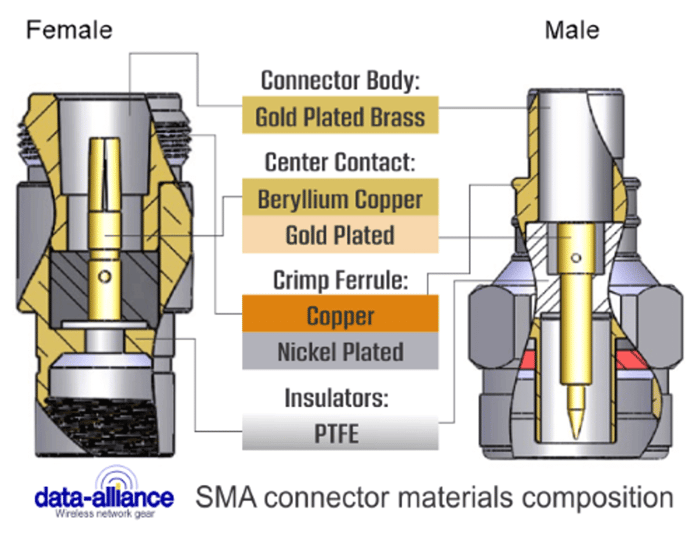
SMA Connector Materials Composition
The materials used in the SMA connector play a significant role in electrical performance, durability, and environmental resistance.
| Component | Material | Purpose |
|---|---|---|
| Connector body (indoor) | Gold-plated brass | High conductivity and corrosion resistance |
| Connector body (outdoor) | Nickel-plated brass | Enhanced rust/corrosion protection for weather exposure |
| Center contact | Gold-plated beryllium copper | Spring pressure over many mating cycles; low oxidation |
| Crimp ferrule | Nickel-plated copper | Strain relief and secure shield termination |
| Insulator | PTFE | Low dielectric loss and thermal stability at RF |
For antennas or cables used outdoors, nickel-plated brass is commonly chosen to balance durability and cost, while gold-plated brass is preferred for indoor applications.
SMA Male and Female Dimensions
Understanding SMA connector dimensions is essential when designing panels, enclosures, or mounting hardware.
- SMA female outside diameter: 5/16 inch (7.9375 mm). This accommodates a hex bulkhead nut with a nominal 5/16 inch outer diameter.
- SMA male inside diameter: 5/16 inch (7.9375 mm). This refers to the internal threaded diameter of the male connector.
Panel Cutouts for SMA Bulkhead Jacks
Anti-rotation "D-hole" (best practice):
- Hole diameter: Ø 6.5 mm (0.256 in)
- Flat dimension: 6.0 mm (0.236 in) across the flat
The D-hole prevents the SMA connector from rotating during installation or when tightening an antenna or cable. Data Alliance's default SMA connector versions include this anti-rotation D-hole, making installation easier and more reliable.
Round hole (common alternative):
- Hole diameter: Ø 6.5 mm (0.256 in)
Round holes are commonly used and can work well when paired with a star or lock washer. However, they do not inherently prevent connector rotation.
Additional Fit and Installation Considerations
Thread and nut:
- SMA bulkheads use 1/4-36 UNS threads.
- Typical panel nut across flats: approximately 8.0 mm (5/16 in).
- Ensure adequate clearance if a socket or wrench will be used during installation.
Panel thickness:
- Short bulkhead versions may support a maximum panel thickness of approximately 2.2 mm (0.087 in).
- Long-thread bulkheads allow for thicker panels.
Always verify panel thickness against the specific connector drawing.
Torque specifications:
- Standard SMA bulkheads: approximately 5 in-lb (0.57 N·m).
- Heavy-duty or hermetic feed-throughs: 12–15 in-lb.
Excessive torque can damage threads, deform panels, or degrade RF performance, especially in plastic enclosures. See our full guide to SMA and RP-SMA torque ratings.
Exceptions to Watch For
Not all components labeled "SMA bulkhead" use the standard 6.5 mm hole size. Certain hermetic feed-through adapters, female-to-female bulkheads, or ruggedized variants may require significantly larger holes—sometimes as large as Ø 0.500 inch. Always confirm the exact panel cutout dimensions using the manufacturer's mechanical drawing.
Quick Installation Tips
- Use the anti-rotation D-hole whenever possible.
- For round holes, use the supplied star or lock washer.
- Do not exceed the recommended torque specification.
- For sealed front-mount connectors (IP67/IP68), ensure the panel finish and O-ring land meet the drawing requirements.
Support and Custom Drawings
If you share the exact SKU(s) you are using, our technical team can provide detailed customer drawings, including DXF and PDF files showing hole size, flat dimensions, and keep-out areas to simplify panel fabrication. Contact technical support or request a custom quote for build-to-spec SMA cable assemblies.
Conclusion
Understanding SMA connector characteristics—from gender identification and material composition to mechanical dimensions and installation best practices—is essential for building reliable RF and wireless systems. Correctly selecting and installing SMA components helps prevent mating errors, minimize signal loss, and ensure long-term performance in cellular, GPS, and industrial applications. By following proper connector selection, panel cutout, and torque guidelines, the SMA connector can deliver consistent, high-frequency performance across a wide range of indoor and outdoor environments.
Footnote: We offer an SMA wrench to assist in installing antennas, SMA cables, and SMA adapters with SMA or RP-SMA connector(s).
Frequently Asked Questions About SMA Connectors
What is an SMA connector used for?
SMA connectors are commonly used in RF and wireless systems such as cellular networks, GPS antennas, test equipment, and industrial communications. They provide reliable performance at high frequencies (DC to 18 GHz) and secure threaded coupling.
How do I tell the difference between SMA male and SMA female connectors?
SMA connector gender is determined by the center contact, not the threads. An SMA male has a center pin, while an SMA female has a center socket, regardless of whether the threads are internal or external.
Why is SMA often confused with RP-SMA?
SMA and RP-SMA connectors look very similar and share the same threaded dimensions, but they have opposite pin-and-socket configurations. They will not electrically mate correctly, even if the threads engage.
What materials are typically used in SMA connectors?
SMA connectors are commonly made with gold-plated or nickel-plated brass bodies, beryllium copper center contacts, PTFE insulators, and nickel-plated copper ferrules to ensure good conductivity, durability, and low signal loss.
What is the frequency range of an SMA connector?
Standard SMA connectors are rated from DC (0 Hz) up to 18 GHz. Precision and extended-performance SMA variants can operate higher, but 18 GHz covers the vast majority of cellular, GPS, Wi-Fi, and industrial RF applications.
Why are proper panel cutouts and torque important for SMA connectors?
Incorrect panel cutouts or excessive torque can cause connector rotation, mechanical stress, or degraded RF performance. Following manufacturer-recommended hole sizes and a torque of about 5 in-lb (0.57 N·m) for standard bulkheads helps ensure a secure, reliable installation.
Can SMA connectors be used in outdoor or industrial environments?
Yes. When properly selected and installed—using corrosion-resistant nickel-plated materials, correct sealing, and appropriate torque—SMA connectors perform reliably in both indoor and outdoor industrial environments.