SMA to RP SMA Cables
LMR-100 coaxial cable: Specifications
Our RP-SMA to SMA Cables we make with LMR-100-equivalent coaxial cable
Used for transmission of radio frequency signals over antenna cables, the LMR-100 is a workhorse in connectivity over distance. Most common uses are:
- broadband internet networks
- audio visual projects
- TV
- computer networks
The LMR-100's features have much in common with other cables within it's class, here are the highlights:
- Copper clad-steel conductor - an efficient and effective vehicle for conveying radio frequency signals
- Dielectric PE foam - insulation layer keeping the signal charge from escaping the cable
- Double shielding - aluminum and copper braiding combination layers for eliminating EMI
- Outer Jacket - maintaining physical integrity in most environments
Composition
1. Inner conductor
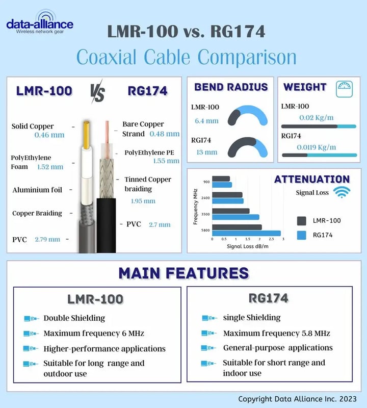
- LMR-100 conductor: 0.46 mm (0.02 in) in diameter
2. Dielectric foam diameter & material
- LMR-100 foam diameter: 1.52 mm (0.01 in), Polyethylene foam
3. Inner shield
- LMR-100 inner shield: aluminum tape
4. Outer shield
- LMR-100 outer shield: copper braiding
5. Outer cable sheath diameter, material & color
- LMR-100 cable sheath: 2.79 mm (0.1 in) in diameter, PVC, black
LMR-100 and it's behavior
Temperature stability = able to withstand temperatures of 85-degrees C the LMR-100 is innately resistant to relative extreme environmental heat. A temperature low of -40-degrees C. Bending radius = flexibility will be your friend with the LMR-100. It will give you the benefit of the tightest bend radius in your chosen application environment: 0.25 inches (6.4 mm) Weight = a very conservatively proportioned product, the LMR-100 proposes great logistical benefits with a weight of only: 0.0092 lb/ft (0.014 kg/m) LMR-100 is made from halogen-free components.
Attenuation
An all-rounder with outstanding conservative features making it a low loss champion among RF signal cables:
At 900 MHz
- LMR-100 = 0.75 dB/m. (0.228 dB/ft.)
At 2400 MHz
- LMR-100 = 1.28 dB/m. (0.389 dB/ft.)
At 3500 MHz
- LMR-100 = 1.58 dB/m. (0.48 dB/ft.)
At 5800 MHz
- LMR-100: 2.10 dB/m. (0.641 dB/ft.)
LMR-100 and double shielding
The LMR-100 internal structure benefits from double shielding. An inner aluminum layer provides 100% coverage minimizing attenuation. An outer copper braiding aides with greater thickness for the ultimate dampening effect on signal seepage.
RP-SMA to SMA Cables
The SMA and RP-SMA connectors are two of the most widely used radio frequency connectors. They are critical components in a wide range of telecommunications and wireless networking applications, including cellular networking, Wi-Fi, Bluetooth, Zigbee, LoRa, satcom, and testing and measurement. Because these two cable types are so common, an SMA to RP SMA cable is indispensable for making connections between radio equipment, antennas, and other components in a variety of settings.
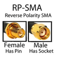
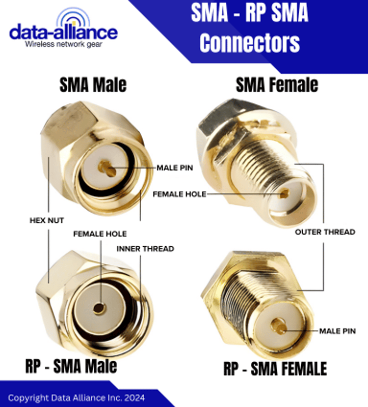
An RP-SMA connector is a reversed polarity SMA connector
SMA and RP SMA connectors are almost identical. The only difference is a reversal of the inner mating interfaces of the male and female connectors.
- A male RP SMA has an inner receptacle rather than the conducting pin that is on the male SMA connector.
- The female RP SMA connector carries a conducting pin instead of the receptacle of the standard female SMA connector.
Though this difference is small, it makes SMA and RP SMA connectors physically incompatible. This incompatibility is deliberate. In the 1990s, electronics manufacturers developed the RP SMA as a compliance measure to deter people from connecting powerful professional antennas to consumer wireless products. Professional equipment routinely carries the SMA connector, while RP SMA connectors are widespread in consumer products.
Physical specifications of the SMA connector
The physical specs of the RP SMA connector are identical, except for the reversed center pin and receptacle (reversed gender). Both male and female SMA and RP SMA connectors are mated by screw-coupling with the tightening of the hex nut on the male connector body. Both types of connectors are rated for 500+ mating cycles. Both connectors come in a variety of formats including right-angled SMA, bulkhead, PCB-mounted SMA connectors, edge-mounted, and panel-mounted.
- Dimensions: the male connector has a diameter of 7⁄16 inches (11 mm) and the female connector has a diameter of 3⁄8 in (9.5 mm)
- Threading: 36 threads per inch
- Material: gold or nickel-plated machined brass with a Teflon insulator
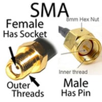
- Male SMA connector: cylindrical body with internalized threads and outer hex-nut for tightening the mated connector with a wrench. Center pin conductor.
- Female SMA connector: cylindrical body with externalized threads, inner beryllium copper receptacle, and silicone rubber gasket
Electrical specifications of the SMA connector.
SMA and RP SMA connectors have identical electrical profiles and performance.
- Nominal impedance: 50 ohms
- Maximum frequency: up to 18 GHz
- Voltage rating: 500 volts.
- VSWR: 1.05 to 1.15 (depending on the attached coaxial cable)
- Contact resistance: 2.0 milliohms.
- Insertion resistance: 5000 megaohms.
- Radio frequency leakage: maximum of -90dB (at 2 to 3 GHz)
SMA to RP SMA cable assemblies
SMA and RP SMA connectors are assembled with a variety of coaxial cables, creating extension cables for antennas and radio equipment. Purchasing a pre-assembled SMA connector cable saves time and provides more reliable results, and you can order custom SMA to RP SMA cables if a specific configuration or length is required that is not readily available.
The compatible coaxial cable gauges for N connector to SMA cables:

