N Female to RP SMA
N-Type Connector to RP-SMA Cables for Antennas
Characteristics and Specifications of the N-Type Connector
The N connector is a medium-sized, threaded radio frequency connector that is designed to conduct microwave frequencies. N connectors are used to connect antennas, coaxial cable, and other radio frequency equipment. It is also known as the N-type connector or Navy connector and is thought to be named after its designer, Paul Neill of Bell Labs, NY. Neill, an American electrical engineer, who designed the connector in the 1940s. It was a novel type of radio frequency connector as is was capable of handling microwave frequencies while being weatherproof and durable. The original design has, over time, been refined with precision improvements to enhance its performance with the multi-gigahertz frequencies in contemporary use.
N connector specs
N connector is manufactured in line with the military standard MIL-C-39012. It is available with either precision, industrial, or commercial-grade fabrication which will affect the cost and the frequency range of the connector. They may be standard N connectors or a helical variant, designed to accommodate corrugated coax.
Physical characteristics of the N-connector
The N connector is a cylindrical connector with an outer diameter of 0.827 inches (20.3 millimeters) for the male and 0.627 inches (15.7 millimeters) for the female. has 5/8-24 United Extra Fine (UNEF) pitch threading. The male and female connectors mate by screw coupling by hand for a weatherproof connection assisted by silicone or synthetic rubber gaskets. N connectors are robust and are rated for 500 mating cycles. Some versions are rated for 5000 mating cycles.
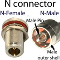
- The male N-type connector (plug) is made from nickel-plated brass. It has internal threads and has an inner mating interface with a silver or gold-plated brass pin conductor. The inner conductor is surrounded by air. Some male connectors also carry a hex nut to assist in tightening.
- The female N connector (jack) is made from brass and has externalized threads and an inner receptacle into which the male pin is inserted. It has no dielectric but carries a gasket to aid a moisture and airtight seal. The receptacle is made from phosphorus bronze or beryllium copper.
Electrical profile of the N-type connector
- Impedance: The N-type connector is available with either a 50 Ohm or 75 Ohm impedance. 50 Ohm N connectors are not fully compatible with 75 Ohm connectors and can cause damage to the connectors if mated. The 50 Ohm connector is widely used in mainstream applications such as wireless networking or amateur radio.
- Frequency range: The typical frequency range of the N connector is DC to 11 GHz. Precision N-type connectors can achieve a frequency range of up to 18 GHz depending on the manufacturer.
- Voltage rating: Voltage rating is important as the center conductor of the mated connector is surrounded by air. The peak voltage rating is 1500 volts.
- VSWR: Voltage Standing Wave Ratio is 1.35
- Insulation resistance: 5000 megohms
- Radio frequency leakage: -90dB at 3 GHz
- Insertion loss: .15 dB maximum at 10 GHz
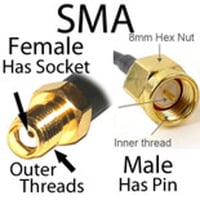
The RP-SMA connector is a reversed polarity version of the SMA connector. It is subminiature, semi-precision, and threaded with identical physical dimensions and electrical performance to the SMA connector. The connector was developed in response to the growth in consumer wireless products in the 1990s to curb the connection of professional-grade antennas to consumer equipment. By reversing the genders of the inner mating interfaces, RP-SMA and SMA connectors are electrically incompatible.
RP-SMA connectors: Characteristics & Specifications
Physical specifications of the RP-SMA connector
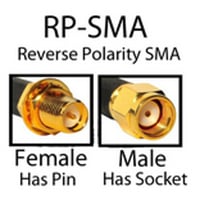
***The inner conductor and receptacle are reversed from the SMA connector configuration***
- Dimensions: the male connector has a diameter of 7⁄16 inches (11 mm) and the female connector has a diameter of 3⁄8 in (9.5 mm)
- Threading: 36 threads per inch
- Material: gold or nickel-plated machined brass with a Teflon insulator
- Male RP-SMA connector: cylindrical body with internalized threads and outer hex-nut for tightening the mated connector with a wrench. Inner beryllium copper receptacle.
- Female RP-SMA connector: cylindrical body with externalized threads, center pin conductor, and silicone rubber gasket
Electrical specifications of the RP-SMA connector.
- Nominal impedance: 50 ohms
- Maximum frequency: up to 18 GHz
- Voltage rating: 500 volts.
- VSWR: 1.05 to 1.15 (depending on the attached coaxial cable)
- Contact resistance: 2.0 milliohms.
- Insertion resistance: 5000 megaohms.
- Radio frequency leakage: maximum of -90dB (at 2 to 3 GHz)
Mechanical characteristics of RP-SMA connectors
- Mating: screw coupling tightened via male hex nut
- Vibration, moisture, and dustproof connection
- Mating cycles: 500+
Type N to RP-SMA extension cables
Cable assemblies that combine the compact RP-SMA connector with the larger and more rugged N connector are an ideal solution for connecting an outdoor antenna to indoor radio equipment. Compatible coaxial cable types for N connector to RP-SMA cables include:
LMR 100 and 200 type coaxial cable is one of the best cables for type N to RP-SMA extension cables. This is because these LMR-type cables are:
- superior fabrication
- highly flexible
- double shielded (with foil)
- low attenuation
Key applications
The RP-SMA connector is prevalent in contemporary wireless networking and is commonly used for the attachment of external antennas that will improve the coverage and performance of networks. Key applications include:

