SMA Extension Cables
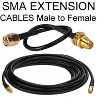
SMA Male to Female Cables for Antennas
Double-shielded coaxial cables of our SMA extension cables:

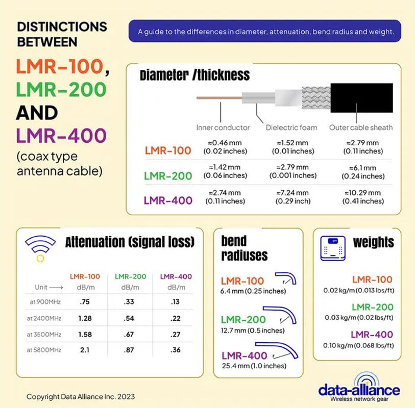
LMR-100-equivalent, LMR-200-equivalent & LMR-400-equivalent are double-shielded, low signal-loss coaxial cable types for antenna cables.
Double-Shielded Low-Loss Coaxial Design: A distinguishing feature of Data Alliance's SMA cables is their double-shielded low-loss coax. This design minimizes signal attenuation and interference, ensuring optimal signal strength and clarity over extended distances.
Durability: The meticulous construction of these cables ensures they withstand external pressures, be it environmental or physical.
Compatible Wireless Protocols and Technologies
SMA extension cables are versatile. They support a variety of wireless protocols and technologies. Among them are:
- Wi-Fi (802.11 a/b/g/n/ac/ax/ah)
- Cellular (GSM, 3G, 4G, and upcoming 5G)
- RFID and NFC
- GPS and satellite communication
- Zigbee and Z-Wave
Their universality ensures they integrate seamlessly with a plethora of devices, further reinforcing their essential nature in the wireless ecosystem.
Torque Ratings of SMA Connectors
Torque rating represents the optimal amount of rotational force that can be applied to the cable connectors without damaging them. Typically, the SMA connectors have torque specifications that should be adhered to during installation. Using a torque wrench ensures that the connectors are neither over-tightened nor too loose, which could compromise the signal.
Materials Composition
SMA extension cables are often made of:
- Center Conductor: Typically made of solid or stranded copper.
- Dielectric Insulation: This component separates the center conductor from the shielding, often made of polyethylene or PTFE.
- Shielding: Double-shielded designs typically involve a combination of foil and braided shielding.
- Outer Jacket: Usually crafted from PVC or a similar durable material, it offers protection against external elements.
An SMA cable extension is a length of coaxial cable which is capped by SMA connectors at both ends. The gender (SMA male plug or SMA female jack), body geometry, and orientation of the SMA fittings can vary as well as the length and type of coaxial cable in the assembly. Types of SMA to SMA extension cables include:
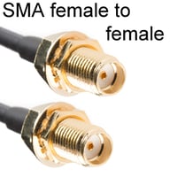
- SMA female to female extension
- SMA male to male cable
- SMA female to SMA female bulkhead adapter cable
- SMA cable male to female coaxial cable
- SMA cable male to male
- SMA female right angle connector cable
An SMA Extension Cable is comprised of coaxial cable terminated with SMA male and female connectors. A coax cable with SMA connectors can be used to increase the range of cable, antennas and devices. SMA male to SMA female extension cable is widely available and can be used in most applications where SMA connectors are present. Data Alliance provides SMA extension cables in a range of lengths from 6 inches up to 150 feet, but it is important to know that there will be a certain loss of power with each meter of length. There are varieties of coax cables that have been designed to be 'low-loss'. LMR-100, LMR-200, and LMR-300 are double shielded coaxial cables that are very high quality, low-loss coax cable in part because of double-shielding and superior durability, especially in outdoor environments.
The SMA Connector: The Sub-Miniature Version A connector, known as the SMA connector is a Radio Frequency (RF) and microwave connector designed to attach antennas to coax cables in a variety of RF applications. As its name describes it is sub-miniature as well as semi-precision and offers a strong and durable 50 ohm impedance connection which can conduct frequencies up to 18GHz and beyond.
Structure and Component Parts of SMA connectors.
SMA connectors look strikingly similar to F-type coax connectors which are typically found in domestic TV set-ups. They are however structurally distinct and cannot connect with the F-type coax. They are manufactured in brass and stainless steel.
As with other RF connectors the SMA connector is composed of male and female parts which mate to form a secure connection. The connection is threaded at 36 thread per inch and screws down to from a very reliable and well favored union which is rated for 500 mating cycles.
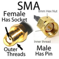
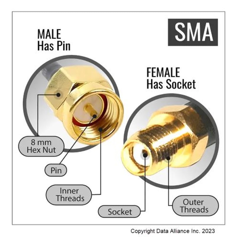
- Male SMA connector has 0.9mm diameter center pin and a barrel with inside threads. Its outer coupling interface has a hex nut which permits tightening with a torque wrench.
- Female SMA connector has a barrel with outside threads that mate with the male connector’s hex-nut. An internal sleeve mates with the male center pin.
- The central pins are supported by a PTFE dielectric in each connector and helps preserve impedance.
SMA Connector Variants:
- Right Angled: Data Alliance provides SMA extension cables with right angled SMA connectors and bulkhead fitting SMA connectors.
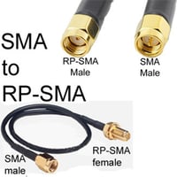
- Reverse Polarity or RP-SMA connectors have a structural reversal of the gender of the each connector's contact pin. A Male RP-SAM has a center sleeve within its threaded barrel and a female possess the center pin with an outer threaded barrel.
Applications of SMA Extension Cables:
SMA extension cables are used to place an antenna in an advantageous position to magnify signal strength with better line of sight. This often means placing an antenna higher, often outdoors, such as on a roof.
The sub-miniature size of SMA connectors, and an operating frequency range of 0 to 18 GHz, lends itself to a variety of RF, VHF, UHF and microwave applications. Highly versatile, they are used as antenna cables in telecommunications for a range of antenna classes. From domestic settings like homes and offices to vast industrial landscapes, the applications of SMA extension cables are manifold.
Key applications of SMA extension cables include:
- Cellular networking: GSM, CDMA, 4G/LTE, 5G
- GPS
- Ham radio
- Satellite and radio astronomy
- Testing and measurement
- LNAs and other radio frequency power amplifiers
- RF isolators
- Radio communication boards
- PCBs
IoT Applications & Wireless Technologies used with SMA Male to Female Cables:
IoT (Internet of Things) is a burgeoning realm, encompassing devices that communicate and share data. SMA extension cables are often used in IoT applications.
- Extended Reach: Enabling devices located further apart to communicate seamlessly.
- Reduced Signal Loss: Ensuring data transmission remains robust.
- Versatility: Their compatibility with a wide array of wireless technologies ensures they can cater to diverse IoT devices.
- Hand-held Radio: SMAs are used in Ham radio. They can connect devices such as walkie-talkies to antennas for greater gain and performance. It is also a type of connector used by many DAB aerials.
- Mobile Antennas: A wide range of mobile antennas, particularly magnetic-mounted varieties, are available which feature the SMA connector. The male SMA connector is typically located on the antenna side with the female on the hardware side.
- WiFi: SMA connectors are not widely used in WiFi equipment, because RP-SMA connectors are particularly favored to preclude consumer use of antennas which could breach compliance.
The SMA connector is a sub-miniature, semi-precision connector that has been in widespread use since the late 1950s. It is made up of threaded male and SMA female connectors that mate by being screwed together and tighter via their hexagonal nut.
- The male SMA connector has internalized threads and an inner conducting pin surrounded by an insulator that forms the mating interface.
- The SMA female jack has externalized threads and a mating interface that features a receptacle into which the male pin will insert.
SMA cables and connectors are attached to the suitable coaxial cable by either soldering or crimping. This can be undertaken as a DIY task, but purchasing pre-assembled SMA connector cable saves time and provides more reliable results. Even custom assemblies can be ordered if a specific configuration or length is required that is not readily available.
Compatible SMA coaxial cable gauges include:
In keeping with the standard impedance of coax cable, the impedance across the entire SMA cable assembly is 50 ohms. The SMA connector can transmit frequencies up to 18 GHz, but the frequency limit of the entire assembly will be determined by the component with the lowest frequency rating.
SMA extension cables have a wide range of applications that are in keeping with the uses of the SMA connector.
They are readily used as SMA antenna extension cable as this class of connector is used in particular for the sma cellular antenna. Aside from SMA antenna cable, this extension cable is used in radio frequency and microwave applications such as:
- Test and measurement
- Instrument panels
- Cellular networking such as 3G, 4G/LTE, 5G
- GPS
- Radar
- Satellite communications
SMA cables Characteristics & Qualities
The characteristics and quality of the SMA extension you choose will affect the overall performance of your radio frequency setup. It is important to competently evaluate the structural and electrical profile of both connectors and cable to ensure that you achieve effective results with minimal loss and interference. Coaxial cable has advantages that, over time, have clearly superseded other types of RF line like twisted pair. It is also a relatively consistent product that is widely available. By understanding the structure and function of both the coaxial cable and SMA connectors, as explained below, you will be better equipped to make a discerning decision on the radio frequency gear you need.
How signal is transmitted through your SMA extension cable.
Your SMA coax cable performs the function of a radio frequency line, transmitting the signal from the source to a termination of your choice, for example, an SMA antenna. The RF line may be the length of the coax or may be made up of multiple SMA extension cables joined by mated SMA connectors. The physical characteristics of both the coax and connectors in your extension cable will largely determine the electric performance of your line and therefore the signal quality that will be achieved by the final assembly.
How RF signal moves down a cable.
Coaxial cable makes an efficient transmission line as the signal is propagated along the cable with minimal loss or alteration. This is due to its outer and inner conductor design that shields from outside electromagnetic interference.
Radiofrequency signal is transmitted down the coaxial cable in Transverse Electromagnetic Mode (TEM), which restricts the electric and magnetic components of the signal to a plane that is transverse to the transmission direction or cable axis. Voltage and current move differently down the coax cable. Voltage determines the electric field and current pulsation generates a magnetic field. The intensity of the electric field is strongest at the surface of the inner conductor. Along a homogeneous length of coax, voltage and current proceed in a constant ratio which is determined by the impedance of the cable.
The physical specifications of your cable will determine performance.
Every coax cable will carry an upper-frequency limit which is determined by the physical characteristics of the coax. Towards the upper-frequency limit waves other than TEM develop and cause disruptive resonances. Also, at higher frequencies attenuation losses increase, making it important that the coax is suitably matched to the transmission frequency. Smaller diameter coax is usually better suited to higher frequency transmission.
Insulation of coaxial cable is the major determinant of impedance.
The impedance of the coaxial cable will depend on the dielectric constant of its insulating material as well as the ratio of the outer and inner conductor diameter. Apart from air, all insulation materials will reduce the speed of signal propagation and wavelength to some degree. Insulating materials like foam, Teflon, and polyethylene each have their own dielectric constant and should be evaluated according to the precision of your radio frequency setup. Reducing the diameter of the inner conductor will increase impedance, but reducing the dielectric diameter decreases impedance.
Interruptions in the cable lead to the generation of reflections.
Interruptions such as gaps, changes in the insulator or conductor diameters, or other physical parameters in an RF line cause a sudden change in impedance of the line and can give rise to reflections of the transmitted signal. Reflections can lead to more than one wave being propagated along the line which degrades the original signal. Each interruption in the RF line will generate a reflection. The transmitted waves will move forward but the reflected RF energy travels back to the source. Lines without discontinuity are known as matched lines. Mismatched lines have interruptions and will generate reflections. This is in part characterized by the Voltage Standing Wave Ratio (VSWR), a ratio between the maximum and minimum voltages along a radio frequency line. VSWR should be as low as possible.
For optimal functioning of the RF system, discontinuity needs to be overcome as much as possible by good connector design and performance and good quality manufacturing of the coax. The number of interruptions in the line should always be kept to an absolute minimum. It is better to have a single 2 meter (6.6 feet) SMA extension cable than two 1 meter (3.3 feet) SMA cable assemblies.
The energy transmitted down the coax cable from the load can be lost to varying degrees before reaching the termination. This is called attenuation and is typically measured per unit of length of a specific cable.
What is a lossy cable?
Lossy lines are cables which have high levels of signal loss along their length. Sometimes this is deliberate (radiating cables), but usually, this is an unfavorable characteristic. Energy transmitted through a coaxial cable can be lost as heat, reflected energy ( which is no longer purposeful and can cause interference), and leakage due to poor shielding. Frequency also plays its part. At frequencies under 10 GHz conductor losses dominate, whereas, above 10 GHz, dielectric losses are more significant. Using good quality coaxial cable in your assembly will minimize this.
The shielding of your cable is critical to effective signal transmission.
Coax needs to be able to maintain the electromagnetic fields as the signal propagates down the line. Shielding is a key means by which these fields are maintained between the inner and outer conductors and is largely performed by an intact dielectric. It prevents unwanted electromagnetic energy from reaching the connector or being lost from it. It is not possible to achieve 100% shielding so some attenuation losses always occur. Both cables and connectors should be shielded to keep RF losses low.
The importance of SMA connectors in an antenna cable assembly.
The SMA connectors in the extension cable perform a number of critical functions:
- To perform as an efficient conduit for radio frequency signals while keeping signal loss and reflections to a minimum.
- To function in line with the attached cable with as much continuity and as little variation as possible.
- To provide access points within an RF circuit, without altering overall performance.
- To operate with convenient and repeatable mating cycles where necessary.
Although it is impossible to fabricate the ideal connector that has homogeneous functioning with its line, radio frequency connector design strives to optimize the electrical and mechanical profile of connectors like the SMA for a unit cost that is not prohibitive. Here are the main mechanical, electrical, and environmental considerations when making a connector selection for your RF setup.
Electrical considerations for the SMA connector
- The frequency limits of the entire assembled RF circuit will be constrained by the component that has the lowest operating frequency, so the connector should match the coax as closely as possible.
- Impedance should match the coax cable as closely as possible, though unavoidable structural steps and discrepancies will mean that there will be discontinuities.
- VSWR structural variances create discontinuities that raise the VSWR.
- Leakage operating frequency and shielding are big determinants of signal loss.
- Insulation resistance is determined by the material and dimensions of the connector's insulator.
Key SMA connector mechanical factors
SMA connectors have proven performance at the sub-miniature level, with notable benefits of the structural design of this connector that enhances its performance and durability. Its threaded design controls the engagement and disengagement forces acting on the connector parts and in particular the male center conductor that is retained in place securely within the female receptacle. It is ideal for test and measurement applications as it is stable and can withstand even severe vibrations.
The coupling nut torque adds extra protection against RF signal loss and is usually achieved with the use of an SMA connector wrench.
Cable retention is critical for the extension cable's longevity and is a key indicator of the quality of the assembly's fabrication. The stability of the cable will be affected by the caliber of soldering or crimping used to assemble the extension and its ability to withstand any mechanical forces acting on it.
Environmental factors
The most significant factor will be whether your cable assembly is used indoors or outdoors. The outside environment and particularly marine challenging for radio frequency applications. Connectors can be made more resilient if they have plating and underplating that resists corrosion. Good quality SMA connectors will also have good temperature and moisture resistance.
Connector materials
Your choice of connector materials will affect the functioning, longevity, and price of your cable. Though SMA connectors are a relatively generic product, attention to the materials that are used to make and plate the connector can advantage your setup.
SMA connectors are made from base materials with further alloying and playing according to the manufacturer's specifications. The materials used in these connectors are selected for their conductivity, ease, and precision of machining and strength. Also, they should be able to withstand the force and extremes of temperature as mentioned above.
Copper is always key for the inner conductor and receptacle lining because of its ability to conduct electricity efficiently. It is typically alloyed (eg. Beryllium copper alloy) or electroplated on the inner conductor of the SMA connector. It is relatively corrosion resistant but care should be taken with prolonged exposure to air, moisture, or chemicals.
Brass
This alloy of copper and zinc is workable and has advantageous thermal and electrical performance when used in the outer housing of the connector. It also has some resilience against moisture, salt, and chemical-laden environments. Plating with Gold or silver further increases its resistance to corrosion.
Stainless steel
This cost-effective option is very hard and has poorer machinability and conductivity than the other metals mentioned, but is a staple for the outer body and housing of the conductor which requires a stronger metal. It is very corrosion resistant in outdoor applications and may be selected for this reason.
Gold, silver, copper, and nickel are commonly used for plating base alloy metals. Plating can be used to:
- Increase conductivity.
- Improve the electrical and environmental performance of the connector.
- Protect conducting parts from surface oxidation or corrosion
- Increase resistance to wear.
- Provide a favorable surface for soldering or other forms of attachment.
Gold alloys are conducive, ductile, and resistant to oxidation. It is frequently electroplated on nickel or copper connector components. Understandably its use comes at a premium, so nickel underplating is often used prior to plating a thinner layer of gold on top.
Silver, a harder and cheaper metal than gold, also confers electrical and thermal benefits when used in the plating of connector parts. Unlike gold, silver does tarnish. Its high conductivity makes it advantageous in conductors and it is also of particular use for solder contacts.
Nickel has widespread use both in alloys and as a plating metal. It conducts heat and electricity well and is easily machined. It works well as underplating for gold and seals of the base metal from any exposure to oxidation.
Frequently asked questions
How can I protect my SMA extension cable in the outdoor environment?
Weatherproofing coaxial cable connections is important because, without adequate protection, gradual moisture ingress into an exposed connection will lead to rust and corrosion of your connectors and cable. This will destroy the assembly and cause shorting that can even destroy an attached antenna. Previously gummy and tar-like materials were used that would damage the performance of the connector and interfere with mating. Special weatherproof coax tape with moldable plastic is widely available and can be used to seal the connector without damaging it. Simply stretch and wrap a length of this tape around the mated connection overlapping as you go. Once covered, press down to ensure that the seal is water and airtight. Removal of the tape is usually straightforward; gently cutaway with a sharp blade over the metal connector, being careful to avoid cutting the cable.
How can I repair a damaged SMA coax extension?
Impacts, abrasions, and compression can damage the coaxial cable. Simple problems like a damaged PVC jacket may be remedied by sealing the exposed area of the cable. If reliability is essential for your RF circuit, you will need to take definitive action. If complete replacement of the length of damaged cable is not possible, cutting out the damaged section of cable, with the attachment of a connector to join up the gap may be an option, or if you have the length to spare, cut off the damaged end of the cable and add a replacement SMA connector.
I have attached an SMA antenna cable to my WiFi antenna. Why isn't it working?
A common and easily remedied reason that a WiFi antenna is not working with an SMA extension cable is that you are using an RP SMA antenna. It is an easy mistake to make as the SMA connector and RP-SMA connector are almost identical in appearance. However, the RP in RP-SMA stands for reverse polarity which means that the gender of the innermost part of the connector is reversed. This means that the male connector will have only a receptacle, while the female RP-SMA will carry the pin. This SMA variant is commonly used in WiFi networking, but if you screw in a female SMA into a male SMA you will have no electrical connection. Disconnect your assembly and check. You may need an RP SMA extension cable.
Can I use an SMA connector cable with the AUX output on my LTE antenna?
4G/LTE antennas usually carry two SMA connector outputs labeled MAIN and AUX. To set up this type of antenna for LTE connectivity, you will actually need 2 antennas:
- the main antenna, which can transmit and receive,
- and an auxiliary antenna that only receives.
The pairing optimizes the performance of 4G and minimizes interference. Alternatively, a GPS antenna can be paired up via the AUX SMA connector if needed. These antennas can be connected together via an SMA cable extension.
DO
- Keep your connectors clean and dust-free
- Use plastic end caps during storage
- Inspect your connectors before assembly
- Align your connectors before mating
- Make the preliminary connection lightly
- Turn the connector nut only to tighten
- Use a torque spanner for the final tightening
DON’T
- Touch the mating surface with your hands
- Use a connector if it is damaged
- Don’t use abrasives or chemicals to clean the connector
- Don’t overtighten the connector
- Don’t bend a mated connector
When handling the coax, avoid pressure and weight on the cable and limit the bend radius as much as possible. Never twist the coax or allow the assembly to support its own weight when vertically installed. If routing a connector, do not pull it through gaps by the connector end. Weatherproof your connectors when installed outside with silicone tape and provide drip loops that allow water to be directed off the cable so it does not potentially settle on a connector.
Rounding up
The SMA connector is a reliable and hardwearing connector choice that can be used to achieve secure RF connectivity in a variety of settings. The range of coaxial extension cable assemblies that feature this widely used connector should make it easy to source the correct cable and connectors for your intended application.

