Tools for Antenna Cables
Antenna Cable Tools
Coaxial cable stripper tools, RP-SMA / SMA wrench, and insertion tools for U.FL and MHF4: High-quality tools for antenna cables and connectors
Hand tools and accessories for coaxial cables and radio frequency connectors are items that are used to:
- strip coaxial cables precisely,
- attach antenna connectors correctly,
- tighten coaxial connectors to the appropriate level of torque,
- and protect exposed unmated ends of radio frequency connectors that are not in use.
Using the correct items when assembling and handing antenna cables will enhance the performance of your radio frequency equipment as well as safeguard its longevity. Coaxial cable preparation tools are used extensively both by professionals, amateurs, and consumers in the following sectors: telecommunications, Satcom, cable TV, testing and measurement, wireless networking, audiovisual, sound engineering, and more.
RoHS compliant coaxial cable tools and accessories
All of our Electrical and Electronic Equipment (EEE) is diligently sourced and compliant with the Restriction of Hazardous Substances (RoHS) directive. Our inventory of tools for antenna cables where applicable also complies with legislation that is concerned with the provenance of Tungsten, Tin, Tantalum, and Gold (3TG) :
- Section 1502 of the Dodd-Frank Act
- The Conflict Minerals Regulation (2021)
Key tools for antenna cables:
The following coaxial cable installation tools and antenna connector accessories can be used to prepare cable to a professional standard. Technicians use the following items to safely and efficiently strip, cut, and terminate antenna cables, as well as tighten mated coaxial connectors. Depending on the type and scale of the radio frequency circuit or network infrastructure installation, these items may have to be used frequently and extensively, therefore they are made to have a long service life with minimal user fatigue. They can be used with confidence in domestic, commercial, and industrial settings.
[A] What is a coaxial cable stripper tool?
A coaxial cable stripper is a hand tool that is used to strip down the jacketing, braid shield, and insulation layers of coaxial cable. This is done by the blades of the stripper scoring the cable layers with the slugs being removed to expose the underlying layers without damaging the cable shielding and conductor. The sharp blades cut through both the various plastic and metal layers of the coax. This is done in a stepped manner leaving the inner conductor exposed with an insulator, shield, and jacket arranged so that they will accommodate the attachment of a compatible connector to terminate the prepared cable. Using a coax stripper is far less prone to operator error, saves time, and delivers consistent results compared to stripping the cable by hand.
Cable strippers come in a range of designs and types and include:
- Drop trimmers
- Coring, stripping, and chamfering tools
- Stripping and chamfering tools
- Some strippers have an integrated crimping tool
The strippers may carry two or three cutting blades and vary in the depth to which they cut the layers of the cables for stripping. They are also sized according to the type and diameter of the coaxial cable that is being prepared, with hex-key adjustable depth and strip length. The cable stripper is designed to not cut the cable too deeply which may be a problem if stripping the cable with a craft knife or other blade. The strip lengths are set to industry standards and the cutting force applied to coax is controlled, reducing the risk of cable distortion. On many designs, a finger hole is present for the operator's finger. The finger is used to depress the blade lever, engaging the blades, and also to rotate the cable stripper on the cable.
[B] What is an insertion tool for the U.FL connector?
U.FL insertion tools are used for connecting and disconnecting the Hirose U.FL connector that is in widespread use in PCB-mounted applications. This miniature connector is more easily handled via this metal jig tool that is accurately conformed to the precise dimensions of this miniature connector. This tool ensures that the connector is inserted and extracted correctly so it does not become damaged as it is fragile and has a limited number of mating cycles.
To unmate a U.FL connector, the end portion of the tool is inserted with its prongs under the flanges of the female connector which then can be lifted off the PCB-mounted male connector in-line with its mating axis.
[C] What is an insertion tool for the MHF4 connector?
An MHF-4 push-pull tool is a specialist hand tool to enable the IPEX MHF-4 connector to be connected and disconnected correctly. The MHF-4 connector has a mated height of just 1.2 inches making the connector difficult to handle. These metal jigs are precisely shaped to fit the dimensions of this fragile miniature connector which is typically surface mounted.
Insertion/Extraction tools like these for the MHF-4 and UFL connectors can be used to extract these delicate connectors from a mating condition without damaging the connector or nearby electronic components. As these miniature connectors are often mounted in component-dense PCB environments the extractor proves an easy and efficient way of disconnecting the connector without disrupting the coaxial cable, connector, or jack.
[D] What is an SMA/RP-SMA connector wrench?
An SMA connector wrench is a type of radio frequency connector torque wrench and an essential tool for the competent mating of standard and reverse polarity SMA connectors.
Both these types of threaded subminiature radio frequency connectors carry an outer hexagonal nut (of 5/16 inch across opposing flats) on the male connector body. The nut is of identical dimensions to a Society of Automotive Engineers (SAE) hex nut.
This flat torque wrench is precisely sized to fit this hex nut and used to tighten it to the appropriate level of torque. The wrench can also be used with adapters too.
With an SMA wrench, standard and reverse polarity SMA connectors can be tightened with precision, meaning that connectors within devices and systems are fully mated and perform properly. The torque wrench is used to prevent under or over tightening of these connectors which can lead to damaged or weakened connections in critical interfaces and impairment of overall system performance. By using a torque wrench technicians can obtain accurate and consistent mating.
[E] What are dust caps?
Dust covers or radio frequency connector dust caps are coverings that are specifically designed to fit the unmated ends of antenna connectors. By covering the exposed ends of connectors, they can be protected from contaminants that may become lodged in the connector threading and the delicate inner mating interface. Because dust caps protect connectors from the ingress of dust and moisture, they help to prevent corrosion which can not only damage the connector but the cable it is attached to. Some dust caps will carry an ingress protection code to specify the degree of sealing they provide.
The SMA connector and its reverse polarity counterpart are widely used radio frequency connectors, used in applications such as cellular and wireless networking and GPS. SMA and RP SMA connector dust covers are useful for protecting connectors while installation work takes place and can be used on a short or long-term basis. During installation, they may be used to prevent static charge build-up in a cable that is about to be connected to an antenna.
As standard and reverse polarity SMA connectors have a structurally identical body, these connector covers can be used to mate with either type of female (jack) connector.
The dust caps can be brass or stainless steel units that are precision machined to mate with these connectors according to MIL specifications. These covers are often impedance matched (and contain an insulator) so that they do not disturb the function of other components in the radio frequency device or circuit where they are being used. Simpler plastic covers that also screw on to the SMA female connector are also available. Some units are fitted with a chain or nylon cord, to prevent the dust cap from being lost from the cable assembly.
Why are tools for antenna cables important?
The use of the correct tools for installing and mating radio frequency connectors minimize discontinuities.
In a perfect radio frequency system, antennas, cables, and downstream devices would have a single uninterrupted line with no structural or impedance variations. This is called a matched line. In reality, radio frequency lines have several discontinuities along their length.
A discontinuity is a location in the line where there is a change in impedance, with a deviation away from the 50 Ohm standard. This can be due to:
- Changes in the conductor or insulator diameter,
- Step changes where cables are terminated by connectors and connectors are mated with connectors,
- Frank gaps, especially in the insulator layer.
Discontinuities created reflections of the electromagnetic waves with both the incident current and voltage being reflected. A line with discontinuities is a mismatched line.
The transmitted waves continue forward and the reflected waves return to the source. Multiple reflected waves will propagate depending on the number and degree of the discontinuities on the line. If the incident and reflected waves meet they cancel each other out leading to short or various degrees of fading depending on the number of reflections that arise.
The objective of selecting, attaching, and connecting antenna cables and connectors with the correct tools and accessories is to keep these discontinuities to an absolute minimum.
Poor handling of connectors when they are installed and mated leads to the generation of passive intermodulation (PIM) products.
If connectors and cables are improperly handled, they can become easily damaged. Irregularities, non-linearities, and other structural variances in the connectors and cables are a cause of passive intermodulation, with the generation of mixed frequency products that cause signal interference that is a problem in cellular and wireless networking.
Key sources of PIM in antenna cables and connectors include:
- Poorly mated connectors with inadequate torque, or those which have been loosened by vibrations, jolts, or other physical impacts.
- Ingress of contaminants like dust, dirt, and moisture.
- Corrosion and its products
- Oil and grease that may prevent pure contact between conducting connector parts
- Metal flakes or solder from the attachment of the connector to the cable.
- Uneven meeting of the metal-to-metal connector surfaces due to overtightening, trapped dielectric material, or warped receptacles.
The above problems can be minimized with correct handling with our selection of antenna cable tools.
Frequently asked questions for tools for antenna cables
How to attach an SMA connector to a coaxial cable?
SMA connectors are often paired with semi-rigid and flexible coax cables such as RG58 or LMR 100 cable in a range of applications. Terminating a coaxial cable with an SMA connector properly will mean that the cable assembly performs properly as mentioned above.
- Identify and separate the connector components (body and center contact).
- Strip the coaxial cable following the connector manufacturer’s instructions. Push back wire braid as mentioned above once the cable is stripped to accommodate the connector body.
- The center contact for the connector should be placed over the central conducting wire of the coaxial cable. The contact should be pushed down so that it sits level with the insulator level. Trim any excess insulation without damaging the conductor wire.
- The center contact can then be either soldered or crimped to the coax wire. The solder should be applied via a hole in the attached contact. If soldering usually 0.020 inches (0.51 millimeter) solder is required.
- Contact and cable can now be threaded into the connector body. Ensure that the cable sits firmly against the insulator within the connector body with no gaps.
- The connector body can either be soldered or crimped to the cable.
- For added protection a heat shrink collar can be used with the connector but this must be threaded onto the cable before the connector is fully assembled.
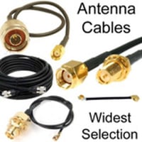
*If you do not feel confident in attaching connectors to antenna cables, purchasing pre-assembled antenna cables is not only convenient but also assures good performance. Browse our selection of high-quality antenna cables here.
How do you mate an RP-SMA connector?
Mating RP-SMA connectors competently make a significant difference to the performance of wireless networking equipment. Bad connections will impair signal quality. Using a wrench to tighten the connector has a discernible effect on microwave frequency transmissions. Here are the steps for connecting RP-SMA connectors properly.
- Inspect your male and female RP-SMA connectors before mating them. They should be clean and undamaged.
- Align the male and female connectors and push them together. This should be a smooth, unobstructed action. Take care when doing this step to ensure that the male receptacle has its center axis aligned with the female pin.
- Rotate the connector at the male hex nut, until finger-tight. Do not rotate the cable or the device. Avoid rotating the center pin within the receptacle as this can damage it.
- Make the final connection by using a wrench. Apply the SMA wrench to the hex nut while holding the female connector body still to prevent the cable or device from turning. This tightening is done to a torque of 3 to 5-pound feet for brass RP-SMA connectors or 7 to 10-pound feet for stainless steel connectors. Tightening should only be done until the “break-point” is reached. Overtightening will damage the connector.
*You may want to wear a grounded wrist strap while handling the cables and connectors to protect yourself from static discharge while you work.
How do you connect an MHF4 connector?
As the world's smallest radio frequency connector, mating and unmating this miniature connector can be extremely difficult by hand. The hinged MHF4 connector plug is designed to receive a piece of suitably stripped micro coaxial cable and is then pushed down to fit the mounted MHF-4 jack. The plug will need to be properly aligned and kept square with the jack before pushing down on top of the plug to make the connection. If there is misalignment the plug often becomes damaged. The push/pull tool makes the aligned opening and closing of this connector simple as it will fit around the top of the plug so that it can be pushed down vertically and lifted off to disconnect.
Can a U.FL or MHF-4 connector be repeatedly connected and disconnected?
Miniature coaxial connectors like the U.FL connector are not designed for a high number of mating cycles. It is rated for only 30 mating cycles. Using the extraction tool will enhance the durability of this connector. The MHF-4 connector is also not designed for repeated reconnections and is similarly rated for 30 mating cycles.
What is the difference between a 2-blade versus a 3-blade coax stripper?
These two types of stripper tools vary in the layers of the cable the tool is capable of removing.
- A 2-blade cable stripper will strip the coax cables outer jacket and dielectric, creating two distinct levels.
- A 3-blade coax stripper will strip three layers of the cable - the outer jacket, shielding, and the dielectric, leaving each layer exposed in a stepped manner.
Stripping the coax to two levels may be advantageous for the attachment of certain connectors. The Type F connector (widely used for audiovisual), in particular, needs a 2 level strip for its attachment. A 3-blade stripper is beneficial for connectors like SMA and RP-SMA connectors
How do you use a coax stripper?
These are instructions for a two-blade coaxial cable stripper. If you are stripping cable for the first time, it may be worth using an excess of cable that you can practice on to ensure you obtain the very best results.
- The orange-colored V-block in the corner of the cable stripper can be adjusted by removing it. This is done by pushing on the V-block from the opposite side (with a screwdriver) and pressing down on the jaw of the stripper to release the V-block. It can then be rotated to accommodate the correct wire gauge of your cable and reinserted.
- The depth of the blades in the stripper will also need to be adjusted for the type of coaxial cable you are using. Take the hex key that comes with the coax stripper and use it to adjust the blades via the Allen screws on the underside of the stripper. Rotating the key will raise or lower the blade to your preferred length.
- Open the jaws of the stripper and insert your cable so that it is flush with the orange V-block.
- Insert your finger into the finger hole and use this to rotate the stripper three times clockwise and 3 times counter-clockwise on the cable.
- You can now remove the cable from the stripper. Do not use the stripper blades to drag the slugs/remnants off the cable. Open the stripper, remove the cable and remove the remnants by hand.
- Fold back the excess wire braid on the coax to allow the radio frequency connector to sit on the stripped coax.
Are there any other accessories for antenna cables and connectors?
Several accessories can be used to protect antenna cables and connectors from environmental damage. Like the coaxial connector dust caps, these accessories prevent the ingress of dust and moisture and should be used when installing cables in an outdoor setting.
- Coax tape is a tacky, stretchy mastic tape that can be wrapped around mated radio frequency connectors and cables. The tape is stretch-wrapped around the connector and coax and molded to provide an insulating and waterproof seal. When access is needed to the connector, it can be carefully cut away and peeled off.
- Silicone grease also known as dielectric grease is an excellent electrical insulator and provides good electrical protection for connectors. It can be spread onto the threading of connectors to provide a barrier that is impervious to moisture and air exposure that can cause corrosion.
- Waterproof couplings are another method of protecting outdoor installations of radio frequency cables. These sealed units house the mated connectors within a sealed body so that it cannot be degraded by environmental exposure. Cable glands may be installed in the walls of outdoor enclosures for a similar purpose.
In conclusion
Being able to handle, assemble and connect antenna cables and connectors properly makes a significant difference to the performance of radio frequency circuits they are used in. The correct tools for antenna cables are essential for assuring the proper installation of radio frequency components and antennas in applications where their function is critical.
LEARN MORE:


